Anyone tried triggering casparcg via GPI port of your switcher assigned to the auto transition button of the switcher? What do I need if this is possible? Thnaks!
Take a look at this post:
It’s fairly easy if you are using custom clients and ATEM switchers. There’s an SDK which lets you grab the M/E status and pass commands to Caspar.
I implemented that in a playout client that triggers a clip on cue when the input is selected or a transition is started to that input.
thanks… How about using other switcher using GPI port.
The CasparCG Client supports doing some stuff with an arduino for GPI.
The thread linked above gives some more info on using that, or some other GPI options
So there are a few ways to do this.
all of them that i know of talk to a client than to a server.
This may be the official Client or others but it is three steps.
https://casparcgforum.org/t/gpio-howto/507
This Tread talks about setting up an arduino to build a GPI for the official client.
it works i have used it. it took me a min to get the hang of it, but it was easy to set up, cheep, and just worked.
most recently i have been using Ross Dashboard (its free) it uses OG script and ross talk
and you can use it to send commands directly to the server.
i use it with a Ross Switcher but you could get it to talk to others as well.
and you would need to know some of the AMPC commands (for CasparCG Link) to do what ever yo need to get the server to do.
but once again the switcher talks to a Client client talks to the server.
And Dashboard is great for making customs control panels as well. and if you have a good tablet or touch screen its like geek heaven.
Ross Dashboard
2 Likes

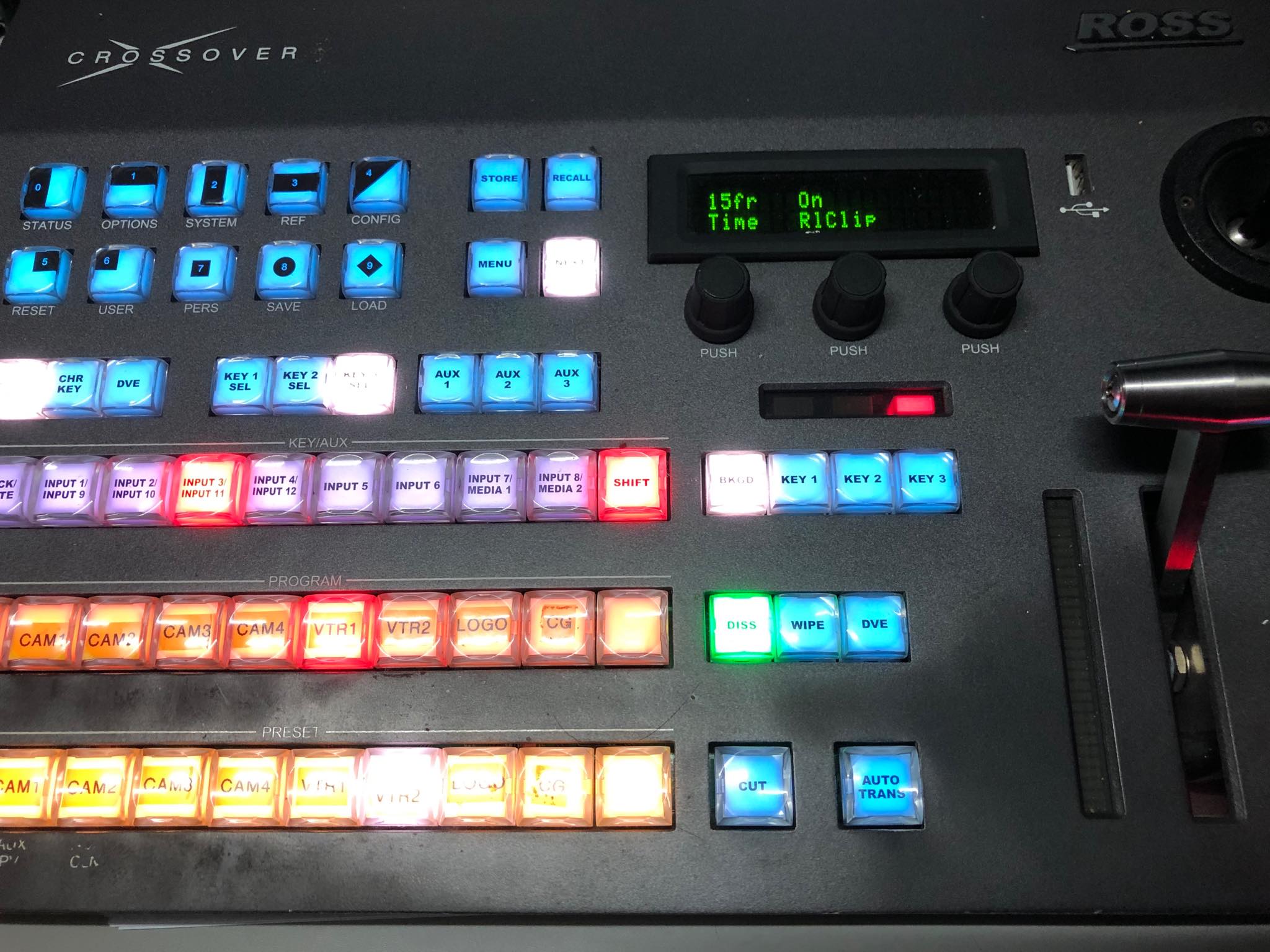
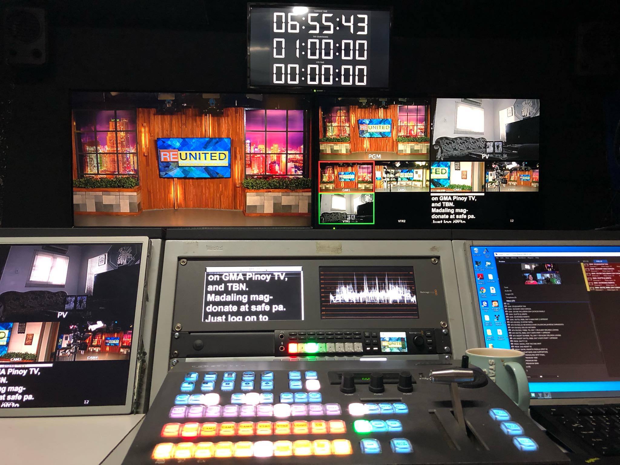
Thanks for the help. I successfully used arduino or numato as GPO trigger to caspar from Ross crossover switcher.
5 Likes
Hi. Can you give me arduino sketch?
Hi! This is where i get the arduino sketch.
https://github.com/CasparCG/Tools/tree/master/cpp/gpio/trunk
Fantastic work David! Looks like you solved it!
Are you able to provide any details about how you got it working?
Personally, I have had some troubles. For example, the sketch hosted on GitHub (arduino_gpio_controller.ino) requires an Arduino library to compile. The “simple_stream_based.h” file also on GitHub would seem to be library, but from my understanding of Aruino libraries, there also needs to be a .cpp file, and both of them need to be contained in a .zip file for the IDE to accept it as a valid library. There are a few .cpp files scattered through the GitHub tools file structure, but none are called “simple_strean_based.cpp” so which if any are associated with the .h file? Or does none of this even make sense??
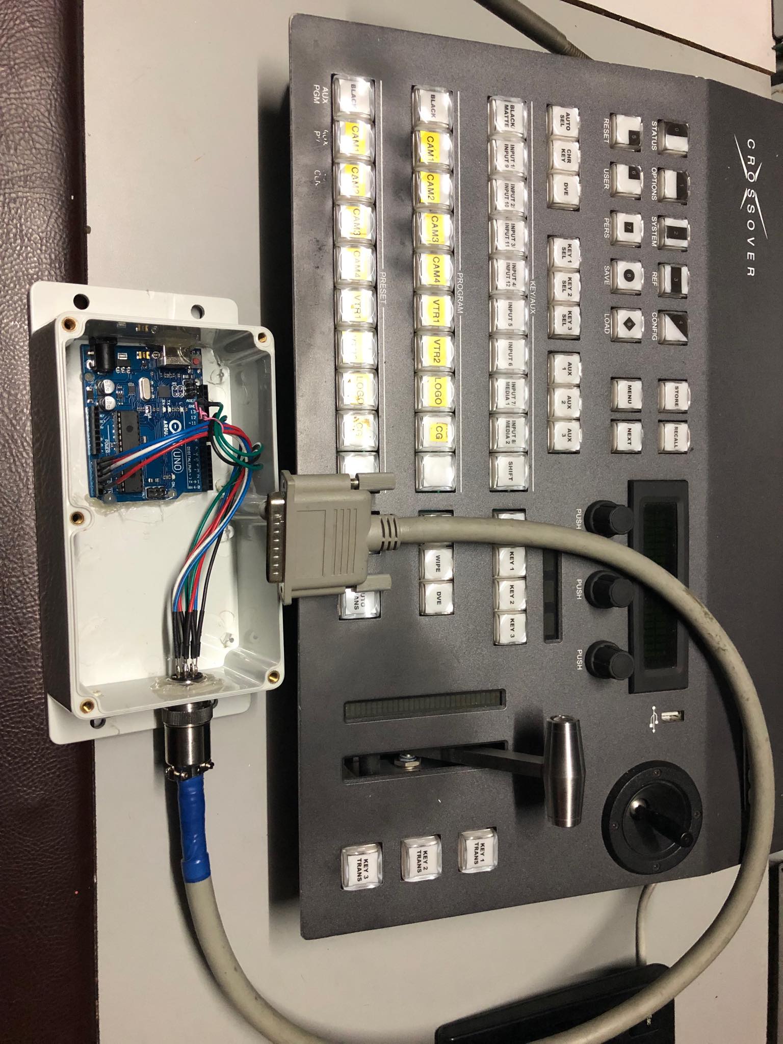
Also, what is the wiring you have going into the Arduino? On the topic that is always referenced when this topic comes up, the Arduino is not actually used, rather a Numato GPIO module. Your photos look like you have both! Are they separate devices? Or did you need both to get it working?
I am happy to do a full how-to and publish it here if I can get it working.
Thanks!
The sketch should contain all that you need to make it work.
When you open the arduino_gpio_controller.ino in the Arduino IDE, you see that includes the simple_stream_based.h file.
This header file contains the inline template classes needed by the sketch, so you shouldn’t need a separate *.cpp file for this one.
Does your compiler complain or return an error when loading the sketch to your Arduino board?
If you load successfully your wiring should be D10,D11,A0,A1,A2,A3,A4,A5 in arduino and thats Pin 1,2,3,4,5,6,7,8 in your GPIO. You must set your switcher GPI output correctly. Then look what COM PORT did you plug your arduino in your computer usb port, mine I used COM7. Then change the settings in your Caspar client GPI device to COM? in serial port and 9600 Baud rate.
The key is your switcher GPIO is working correctly or configure correctly so it would work.
YES! I was able to make the numato module work with the GPI but somehow some of the channel are shorted they send me a defective module. So I used the arduino instead and work perfectly with my setup.
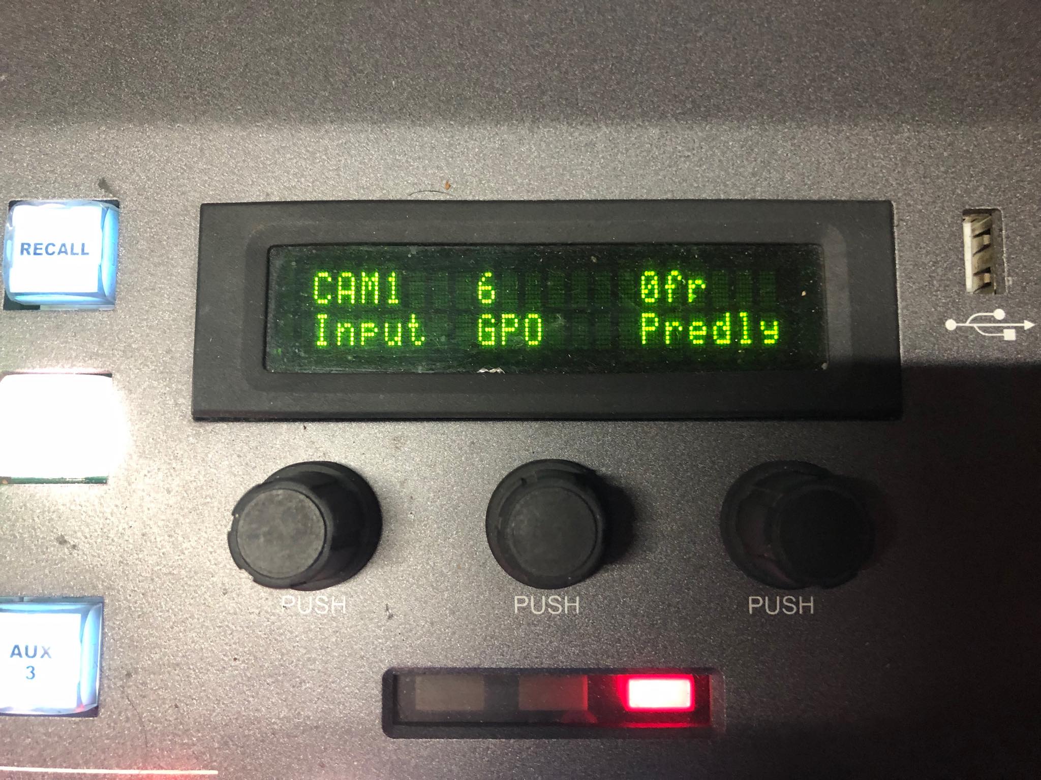
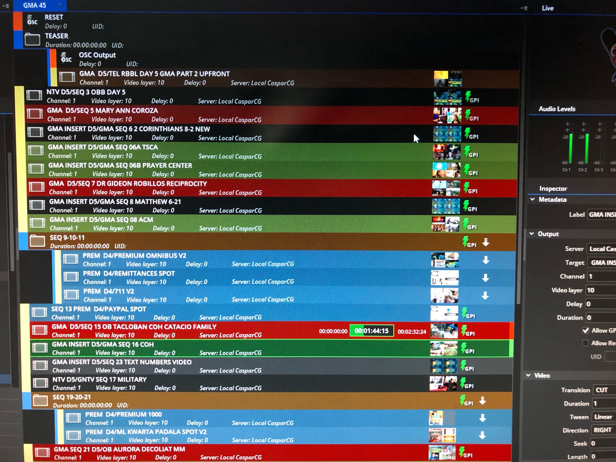
With my GPIO settings in my switcher I set my VTR input to 3 means PlayNOW, and Remaining Input to 6 means LOAD. So everytime I used MIX it trigger the caspar to play what is loaded. Also check the Allow GPI in the client.
Hope it helps,
https://www.facebook.com/profile.php?id=567599922
1 Like

Thank you so much!
I’ve managed to get the Arduino sketch to load properly - I don’t know what I was doing wrong before when it wouldn’t compile and would complain about the library not being valid (probably just files in the wrong place in my local directory structure - for future readers, the “simple_stream_based.h” library file should be in the same folder as the “arduino_gpio_controller.ino” file, NOT in the Arduino IDE “library” folder.
I’m now wiring up the arduino to test, and shall report back with my results.
In the meantime, I did manage to get an alternate method working using a Raspberry Pi (connected to the same local network as the CasparCG PC) and a python script - it’s not ideal compared to a USB connected arduino, but would allow more options (remote GPIO over LAN/WAN/web etc). If anyone is interested in a more thorough explanation of how to do this, let me know and I’ll do up a howto.
Thanks!
Nice work! I have Raspberry Pi but used it for TIMER.
1 Like
Hi everyone. I’m new here and I have a question about GPIO output. I have an arduino with code from github, Input’s working fine, but i don’t know how to use GPI output from client to control the switcher. Is it possible with this sketch?
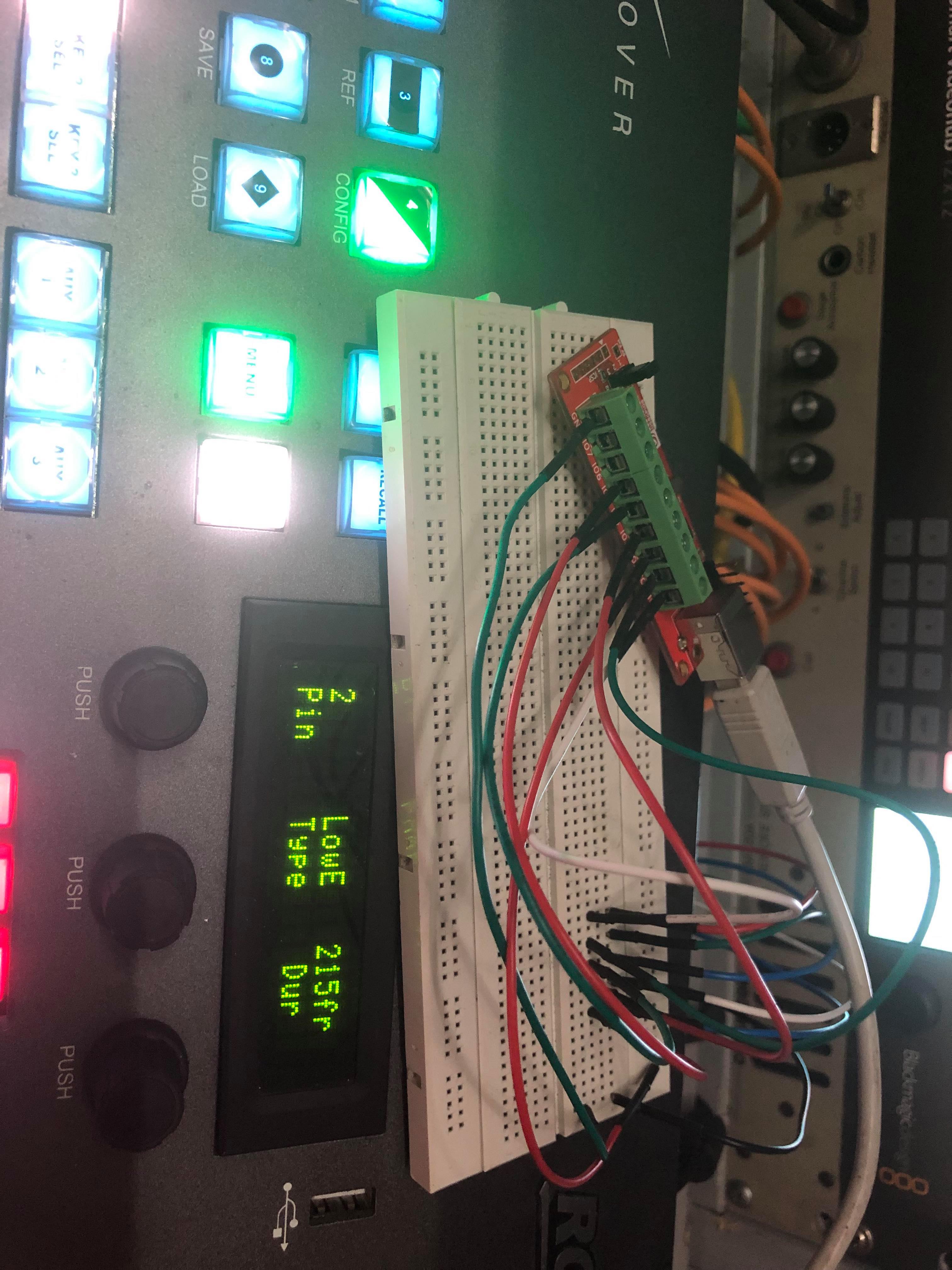
It is possible to control many items of equipment via the CasparrCG client GPI Arduino sketch. Arduino Uno pin numbers 2 through 9 are programmed as GPI outputs 1 through 8. The CasparCG client configuration defines the normal output state for each GPI output (rising edge is normally low, falling edge is normally high) and the duration of a pulse on that output pin.
If your switcher GPI inputs expect pulses rather than DC levels you can, with care, connect the Arduino pin to the switcher to be controlled. Some switchers allocate dedicated pins for GPI functions, others have a set of pins for GPI input, and the function of each pin is defined in the switcher configuration.
If the switcher needs DC states for control you need extra circuitry that uses two connections from the Arduino, one connection switches the control state to off (open), the second connection switches the control to on (closed). Alternately you need to modify the sketch code to implement the DC switching.
A problem with GPI inputs and outputs is the interface technical properties are not defined by any standard, and hence implementation differs between devices.
The general concept is the GPI input requires a closing contact on a switch/relay. That switch/relay closing causes current to flow in an opto-isolator in the controlled equipment, indicating the control active condition. The opto-isolator needs a source of power to provide the current. That source power can be provided by an internal source in the controlled equipment, or provided by an external voltage source. Some equipments support internal and external supplies, selection is configured by simple links/switches on the interface card. Hence the voltage presented at the GPI input terminal can vary with equipment. Most modern kit can use an internal 5V DC supply.
If the receiving input uses internal 5V power for the input stage it is possible to connect the Arduino output pin direct to the equipment to be controlled, with the Arduino 0V connected to the equipment GPI common pin. Just check that the Arduino can source or sink the required current for the equipment you connect into.
If you are connecting to a range of devices it may be better to add a small relay interface board that connects direct to the Arduino providing isolation of supplies. Plenty of avilable relay boards are available for Arduino and Raspberry PI units via Amazon and similar outlets. Two example modules are 2ch relay and 8Ch Relay.
Hi! Thank You very much for help, now everything is clear for me. Also i found a wrong configuration in mixer setup, because it have 3 ports for tally/gpio.